In fast-paced manufacturing and product development environments, slow prototyping cycles and expensive tooling can paralyze project timelines. Whether you are validating a complex pipe routing assembly or fabricating custom stamping dies, traditional subtractive manufacturing often introduces bottlenecks and higher cost. Most files required for FDM printing are related to STL file format, however user can use AV View MultiCAD Viewer if other file format are available as in case of proprietary software.
Fused Deposition Modeling (FDM) has evolved far beyond basic desktop prototyping into a vital industrial manufacturing technology. For application engineers, 3D designers, and tooling specialists, industrial FDM printers offer a direct path from CAD models to production-ready end-use parts, functional prototypes, and custom shop-floor tooling.
What is Fused Deposition Modeling (FDM)?
Fused Deposition Modeling (FDM)—also referred to as Fused Filament Fabrication (FFF)—is an additive manufacturing process that builds 3D parts by melting and extruding thermoplastic filament layer-by-layer through a heated nozzle. FDM has many benefits in the manufacturing process over the traditional manufacturing process.
How FDM Works for Technical Applications
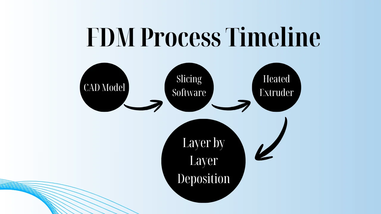
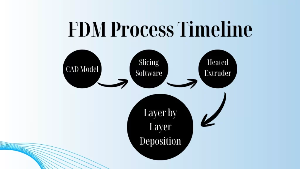
- G-code Generation: Slicing software converts 3D CAD geometry into toolpaths, calculating infill patterns, wall thickness, and support structures.
- Extrusion & Deposition: The printer heats thermoplastic filament to its precise glass transition temperature and deposits layer thicknesses typically ranging from 50 to 400 microns.
- Cooling & Bonding: Layers thermally fuse together almost instantly upon deposition, forming a solid, cohesive component ready for mechanical load testing.
Strategic Benefits for Application, Design, and Pipe Engineers
Rapid Functional Prototyping & Iteration
For design engineers, waiting weeks for CNC-machined prototype revisions slows innovation. FDM allows design teams to print functional prototypes overnight, perform fit-and-function testing early in the design phase, and refine models before committing to expensive tooling injections.
Custom Jigs, Fixtures, and Die Design
Die designers and tooling engineers frequently leverage high-strength FDM thermoplastics to fabricate soft tooling, sheet metal forming dies, and assembly jigs.
Key Takeaway: Replacing CNC-machined aluminum jigs with carbon-fiber-reinforced FDM parts can reduce tooling weight by up to 70% and cut fabrication costs by 80%.
Complex Pipe & Routing Layout Mockups
Pipe and routing designers face unique spatial constraints when laying out fluid power systems, HVAC, or industrial piping runs. FDM enables full-scale or scaled physical mockups of intricate manifold designs and tight-radius pipe bends, helping engineering teams identify spatial collisions and clearance issues before final installation.
Selecting Engineering-Grade FDM Materials
Choosing the right material is essential to match mechanical requirements like tensile strength, thermal resistance, and chemical exposure:
| Material | Key Characteristics | Common Engineering Use Cases |
| ABS / ASA | High impact resistance, UV stable (ASA), easy to machine | Enclosures, automotive interiors, ductwork mockups |
| PETG / Polycarbonate (PC) | High heat resistance, structural rigidity, flame retardant | Functional mechanical components, electrical housings |
| PA-CF (Nylon Carbon Fiber) | Superior strength-to-weight ratio, stiffness, chemical resistance | Metal replacement parts, custom jigs, end-effectors |
| PEEK / PEKK | Extreme heat (up to 250°C), chemical and chemical resistance | Aerospace components, oil & gas manifold fittings |
FDM vs. SLA & SLS: Industrial Cost & ROI Comparison
When selecting an additive manufacturing ecosystem for industrial workflows, comparing capital expenditure and functional output is critical:
- FDM (Fused Deposition Modeling): Best for large-scale parts, high-strength structural materials, and low-cost shop floor tooling.
- SLA (Stereolithography): Best for ultra-high surface detail and fine features, though resins generally offer lower thermal and impact resistance compared to thermoplastics.
- SLS (Selective Laser Sintering): Excellent for complex, support-free geometries and low-volume production runs, but requires significantly higher initial capital expenditure and powder handling infrastructure.
Key Considerations Before Buying an Industrial FDM Printer
Before investing in commercial FDM hardware, application and procurement engineers should evaluate four key hardware features:
- Build Chamber Temperature Control: Actively heated build chambers (above 60°C) prevent warping and layer delamination when printing high-temperature polymers like PC or PEEK.
- Dual Extrusion Capabilities: Independent Dual Extruders (IDEX) allow the use of soluble support materials (e.g., PVA or Breakaway), enabling complex internal geometries and hollow piping runs.
- Open Material Ecosystems: Printers that accept third-party filaments offer significantly lower long-term material consumable costs compared to locked proprietary systems.
- Nozzle Temperature Capabilities: High-temperature hotends (reaching 400°C–500°C) are required if your engineering scope includes advanced composite filaments.
Conclusion: Accelerate Your Engineering Workflow with FDM
Fused Deposition Modeling is a core asset in modern industrial engineering workflows. By integrating high-performance FDM 3D printing into your development pipeline, your engineering team can drastically shorten design cycles, cut tooling lead times from weeks to hours, and validate complex mechanical layouts with complete confidence.